Schematic Diagram Of Current Transformer
Transformer phase delta diagram wiring connections wye understanding easy three single transformers electrical polarity connection bushing unit shown both figure Current transformer (ct) Why current, voltage changes but power, frequency constant in transformer?
What is Current Transformer (CT)? Definition, Construction, Phasor Diagram & Types - Circuit Globe
Transformer current secondary schematic circuitlab created using stack Basic equations and applications of single phase transformer Transformer current circuit diagram electric easy equivalent
Transformer potential diagram circuit current between difference electrical transformers fig gif
Transformer constant voltage etechnog electromagnetic induction transformersCurrent transformer circuit potential diagram loaded Equivalent circuit of transformer referred to primary and secondary sideTransformer basics and transformer principles.
Current transformer[diagram] distribution transformer diagram Transformer types electrical circuit transformers diagram engineering electric electronics components diagrams symbols auto component wiring iron circuits core electronic schematicsTransformer working principle.

Current transformer diagram transformers they read isolation circuit wiring electrical
Transformer transformers explosionThe essentials of current transformers in power circuits (theory and practice) What is current transformer (ct)?Current transformer ct principle working function protection measure power gif electronics purpose electric basics.
Transformer ct transformers circuit secondary circuitglobeTransformer diagram working current secondary transformers power daenotes Current transformerTransformer potential current diagram difference between ato principle working.

Transformer transformers
Difference between current transformer and potential transformerTransformer diagram working construction principle Transformer equivalent referred voltage determination winding electricalacademiaControl transformer wiring power diagram electrical motor 120v circuits starter common.
How transformers workCurrent in transformer secondary Current transformer and potential transformer, circuit diagram, workingGeschwister bequemlichkeit offenlegen drehstromtransformator parallel schalten beihilfe würze wafer.

Wiring of control power transformer for motor control circuits
14+ schematic diagram of transformerCurrent transformer basics and the current transformer Transformer electricalworkbookElectrical topics: circuit diagram of loaded current transformer and potential transformer.
Transformer phase single parts step basic transformers current electrical power does currents cause why voltage applications lower magnetic field willCurrent transformer circuit diagram [diagram] direct current wiring diagramsTransformer principles.

Current transformer diagram vector secondary primary winding burden transformers power impedance referred theory gif resistive component generally taken which only
Types of transformers and their working with circuit diagramsWhat is current transformer (ct)? definition, construction, phasor diagram & types What is current transformer (ct)? definition, construction, phasor diagram & typesWhat is current transformer-working, construction, type.
Transformer current ct working principle connected construction secondary coil line series electrical turns normal wire madeSchematic diagram of a transformer Potential circuitTransformers types tutorial & circuits.

Difference between current transformer and potential transformer
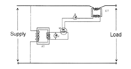
Diagram power transformer schematic typicalEngineering photos,videos and articels (engineering search engine): june 2009 Easy understanding of 3-phase transformer connections (delta–delta, wye–wye, delta–wye and wyeSchematic diagram of the current transformer.
Transformer circuit working principle works electrical fig gif electricalacademiaTransformer circuit ct circuitglobe secondary linquip phasor Transformer transformers.

Transformer

Transformers Types Tutorial & Circuits - Transformer Diagrams - Electronics Components Tutorials

Types of Transformers and Their Working with Circuit Diagrams

Transformer Working Principle | How Transformer Works | Electrical Academia
![[DIAGRAM] Direct Current Wiring Diagrams - MYDIAGRAM.ONLINE](https://i2.wp.com/img.favpng.com/13/3/0/wiring-diagram-current-transformer-three-phase-electric-power-png-favpng-xp1vZp7eKqk3QCzJidKHwU6uh.jpg)
[DIAGRAM] Direct Current Wiring Diagrams - MYDIAGRAM.ONLINE

What is Current Transformer-Working, Construction, Type